![]()
Bridge magazine features design, construction
of Interstate 84/Ten Mile Road interchange
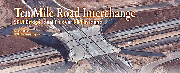
The following feature appeared in the Summer 2011 edition of Aspire Magazine, which focuses on bridge design and construction. The quarterly publication featured Idaho's I-84/Ten Mile Interchange, completed in May. The I-84/Ten Mile Road Interchange project in Meridian, will add much needed interstate access for a growing community.
Ted Bush, HDR Engineering
The interchange improves connectivity along I-84 and replaces an existing overpass. Five interchange types were considered. The standard single-point urban interchange (SPUI) was selected based on several factors, including construction cost, right-of-way impacts, anticipated year 2030 level of service, and environmental issues. The project also features widening of both Ten Mile Road and I-84, mechanically stabilized earth (MSE) walls, and a culvert.
SPUIs are becoming popular in urban areas throughout the United States due to their compact layout and efficient traffic management. The typical hourglass shape of SPUI structures, however, results in a geometrically complex bridge with complicated structural behavior. This SPUI is an innovative solution for this region; the first designed in the state of Idaho and only the second SPUI constructed there.
 Evaluation of Alternatives
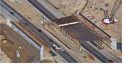
Given the unique shape of SPUI bridges, framing configurations need to be carefully considered to minimize unused deck area and account for multi-directional load paths. Several alternatives were investigated. For each of the superstructure types evaluated, the design team developed conceptual designs and cost estimates. An important benefit of the project was the opportunity to replace the existing five-span structure with a single-span bridge that would accommodate widening of I-84 under the bridge.
A single-span bridge would improve motorist safety by increasing visibility and eliminating a potential collision hazard. It also would reduce material requirements, construction duration, and impacts to median construction operations. The additional structure depth required by the single-span bridge was accommodated by modifying the vertical profile of both the I-84 and Ten Mile Road approaches in the early stages of design.
Based on conceptual evaluations, the design team recommended a single-span, cast-in-place, post-tensioned concrete box-girder bridge with a splayed framing plan. In addition to lower construction cost, the recommended structure type reduced the tunnel effect caused by alternatives featuring larger bridge widths.
It also provided future flexibility for median related construction activities by eliminating the center pier. The stiffness and redistribution characteristics of the bridge offered excellent structural performance. Since there was no unused deck area, the bridge did not require additional safety railings and resulted in a more aesthetically pleasing appearance. Another benefit of the superstructure type was the provision for an enclosed, protected area for utilities.
Design Features
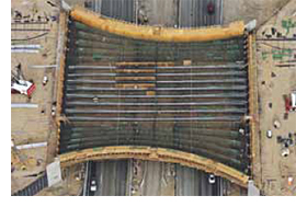
The 189-ft.-long structure forms an hourglass shape with a variable width ranging from 158 to 206 ft. A minimum edge of deck radius of 200 ft. offered improved constructability and controlled out-of-plane bending effects imposed on the curved girders. The bridge can accommodate future expansion of an additional lane in each direction along Ten Mile Road and an additional I-84 off-ramp left turn lane. A constant 1.4 percent vertical grade and 1 percent normal crown slope were specified for the interchange due to roadway stopping sight distance and drainage requirements.
 The 8-ft 6-in.-deep cross section includes 10 straight girder webs in the center with five curved girder webs on each side. The straight girder webs are 12 in. thick and spaced at 9 ft. 9 in. The curved girder webs are 15 in. thick with a spacing that varies from 5 ft. 6 in. to 13 ft. 2 in. The deck is 8 1/2 in. thick and the bottom slab 6 in. thick.
The top and bottom flanges and girder webs are thickened near the abutments to accommodate the general zone anchorage design and the larger web spacing required near the southwest and northeast corners of the bridge. Long-term durability and corrosion resistance to satisfy the minimum 75-year service life were addressed by the use of a one-inch thick expendable (nonstructural) top deck slab wearing surface, epoxy-coated reinforcement for the top deck slab and girder web reinforcement, and multi-levels of protection for the post-tensioning system.
The post-tensioning varied within the cross section due to curvature and variable web spacing. The curved girder webs required three tendons and the straight girder webs had four. All tendons used 0.6-in.-diameter low-relaxation strands. A varying post-tensioning force was used for the exterior curved portions of the structure to account for the friction loss difference from the varying radius and length of tendons.
A jacking force of 3603 kips was specified for the straight webs while 3,032 kips, 3,076 kips, 3,120 kips, 3,164 kips, and 3,208 kips were specified for the curved webs. The resulting total structure jacking force of 67,230 kips was applied through a total of 1,530 strands. Commercial, Post-Tensioning Institute Type C prepackaged, thixotropic grout was used in the ducts to encase the tendons and injected from the low point at Abutment 2 toward the vents at mid-span and Abutment 1.
 The superstructure is supported on 25-ft.-tall, free-standing, cast-in-place concrete seat-type abutments. Given the hourglass shape of the superstructure, the abutment locations were designed to minimize the abutment lengths and provide the minimum horizontal clearance required to meet the anticipated ultimate build-out of I-84.
The abutments are founded on three rows of 18-in.-diameter steel piles. A combination of single- and two-stage, welded-wire reinforced mechanically stabilized earth (MSE) walls support the ramp and Ten Mile Road approaches. It was determined to be more economical to support the Ten Mile Road approach fill using a single-stage MSE wall rather than designing the abutment to resist lateral earth pressures. This resulted in a void between the two components that required many design and detailing revisions to the conventional approach slab.
Garrity Boulevard
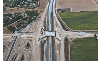
In several separate projects, the Idaho Transportation Department and Connecting Idaho Partners are also widening the interstate corridor within the Boise area to accommodate the high traffic demands caused by commuting motorists. The project team coordinated extensively with these adjacent separate projects throughout design and construction. The new Ten Mile Road SPUI opened at the end of May 2011.
 The required minimum concrete compressive strength of the box girder superstructure was 5,000 psi at 28 days and 4,000 psi at the time of post-tensioning. All other structural components required a minimum concrete compressive strength of 4,000 psi at 28 days.
The Right Bridge at the Right Time
I-84 serves as a vital link for transportation in Meridian and the surrounding area. It is the only interstate highway that provides a continuous direct connection between the states of Utah, Idaho, and Oregon. The new interchange is located within a heavily used six-mile section between existing interchanges at Meridian Road and Garrity Boulevard. In several separate projects, the Idaho Transportation Department and Connecting Idaho Partners are also widening the interstate corridor within the Boise area to accommodate the high traffic demands caused by commuting motorists. The project team coordinated extensively with these adjacent separate projects throughout design and construction.
Profile: Ten mile road interchange over I-84 / Meridian, Idaho Bridge design Engineer: HDR Engineering Inc., Boise, Idaho |
Published 8-12-2011